Ideas & Solutions
The effect of etch factor on printed wiring characteristic impedance
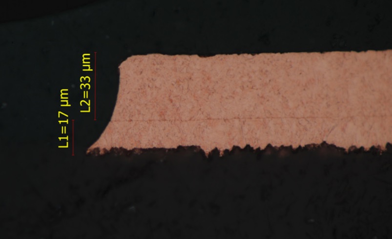
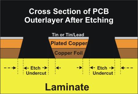
As logic switching speeds continue to increase, signal integrity becomes increasingly important. The signal paths have to be treated as transmission lines to accurately predict signal integrity. Many software tools exist to calculate transmission line characteristic impedance of printed-wiring traces as part of the overall signal analysis. As the logic speeds get even faster, the effect of transmission line mismatch becomes more serious. Many of the software tools assume a rectangular cross-section for the traces. In actuality, the trace cross-sections more closely approximate a trapezoid due to the etching process (see pictures).
 Steve Monroe and Otto Buhler from Storage Technology Corporation have used a field modeling program to determine the characteristic impedance of a variety of traces including buried microstrip, symmetrical stripline, edge-coupled pair, and broadside-coupled pair. These impedance determinations were performed with both rectangular and trapezoidal cross sections. In some cases, the difference in characteristic impedance between rectangular and trapezoidal cross-sections exceeded six percent which gives you a serious additional deviation even within typical 10% factory tolerance for impedance control. More about this you can find here.
Please contact our engineers when you design your new PCB project with controlled impedance, and we will help you to build a proper stack-up with impedance calculation based on real factory capabilities and experience.
Steve Monroe and Otto Buhler from Storage Technology Corporation have used a field modeling program to determine the characteristic impedance of a variety of traces including buried microstrip, symmetrical stripline, edge-coupled pair, and broadside-coupled pair. These impedance determinations were performed with both rectangular and trapezoidal cross sections. In some cases, the difference in characteristic impedance between rectangular and trapezoidal cross-sections exceeded six percent which gives you a serious additional deviation even within typical 10% factory tolerance for impedance control. More about this you can find here.
Please contact our engineers when you design your new PCB project with controlled impedance, and we will help you to build a proper stack-up with impedance calculation based on real factory capabilities and experience.
Hide topics
